2 Wire Pressure Transducer Working Principle and Structure
In industrial applications, 2 wire pressure transducers are definitely the first choice. In industrial production, the measuring points are generally on site, and the display device or control device is generally in the control room or control cabinet. The distance between the two will be tens of meters or even hundreds of meters. Eliminating two wires means that the cost can be reduced a lot.
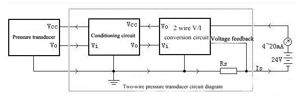
From the overall structure point of view, the two-wire pressure transducer consists of three parts: sensor, conditioning circuit, two-wire V / I converter. The sensor converts physical quantities such as pressure and liquid level into electrical parameters. The conditioning circuit amplifies and conditioning the weak or non-linear electrical signals output by the sensor, and then translates it into a linear voltage output. The two-wire V/I conversion circuit controls the overall power consumption current according to the output of the signal conditioning circuit. At the same time, the converter takes the voltage from the loop and regulates it for use in conditioning circuits and sensors. In addition to the V/I conversion circuit, each part of the circuit has its own current consumption. The core design idea of the two-wire pressure transducer is to include all current in the feedback loop of the V/I converter.

As shown in the figure, the sampling resistor Rs is connected in series at the low end of the circuit. All current will flow back to the negative pole of the power supply through Rs. The feedback signal taken from Rs contains the power consumption of all circuits. In a two-wire pressure transducer, the total power consumption of all circuits cannot exceed 3.5mA. Therefore, the low power consumption of the circuit becomes a major design difficulty. The principle and design points of each part in the circuit will be analyzed one by one below.


1. Power protection
Power supply reversal, overvoltage, and surge are common power problems in the industry. The reverse connection of the power supply is the most common error when installing and wiring for the pressure sensor. Connect a diode in series with the input port to prevent damage to the circuit when the power supply is reverse connected. In order to prevent lightning, electrostatic discharge, surge and other energy damage to the pressure transducer, a TVS tube can be installed at the entrance of the transducer to absorb the instantaneous overvoltage energy. If it is possible to suffer a major lightning strike, the capacity absorbed by the TVS may not be sufficient, so a varistor can be used. It should be noted that the leakage of the varistor itself will cause a certain measurement error.
2. Overcurrent protection
During the operation of the equipment, the pressure transducer may have problems such as disconnection or short circuit. The input volume itself is likely to exceed the range. For pressure transducers, it must be ensured that the output will not rise unrestricted under any circumstances, otherwise the transducer itself, the power supply, or the remote display instrument will be damaged.
3. Wide voltage adaptability
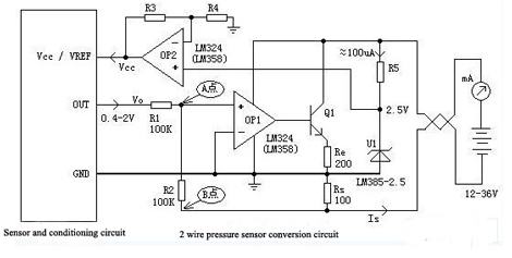
In general, two-wire pressure transducers can accommodate a wide range of voltage changes without affecting accuracy. It allows for a wide range of power supplies and accommodates large load resistors. The most sensitive part to the power supply is the reference source, and the reference source is also the main component that determines accuracy. The reference source is current limited by a resistor. When the power supply voltage changes, the current on the resistor also changes, which has a great influence on the stability of the reference source. Powering the reference source with a constant current source. When the voltage is widely changed, the current is unchanged basically, thereby ensuring the stability of the reference source.
4. Decoupling capacitor
In general, in the circuit design, there is a decoupling capacitor at the power supply end of each integrated circuit. When the two-wire pressure transducer is energized, because the capacitor is charged, it will cause a large current in an instant, which may damage the remote meter. Therefore, for a pressure transducer, each decoupling capacitor generally does not exceed 10nF, and the total decoupling capacitance should not exceed 50nF.
- Structure and principle of 2 wire pressure transducer
From the overall structure point of view, the two-wire pressure transducer consists of three parts: sensor, conditioning circuit, two-wire V / I converter. The sensor converts physical quantities such as pressure and liquid level into electrical parameters. The conditioning circuit amplifies and conditioning the weak or non-linear electrical signals output by the sensor, and then translates it into a linear voltage output. The two-wire V/I conversion circuit controls the overall power consumption current according to the output of the signal conditioning circuit. At the same time, the converter takes the voltage from the loop and regulates it for use in conditioning circuits and sensors. In addition to the V/I conversion circuit, each part of the circuit has its own current consumption. The core design idea of the two-wire pressure transducer is to include all current in the feedback loop of the V/I converter.

As shown in the figure, the sampling resistor Rs is connected in series at the low end of the circuit. All current will flow back to the negative pole of the power supply through Rs. The feedback signal taken from Rs contains the power consumption of all circuits. In a two-wire pressure transducer, the total power consumption of all circuits cannot exceed 3.5mA. Therefore, the low power consumption of the circuit becomes a major design difficulty. The principle and design points of each part in the circuit will be analyzed one by one below.
- Design of 2 wire pressure transducer


- 2 wire pressure transducer stability and safety considerations
1. Power protection
Power supply reversal, overvoltage, and surge are common power problems in the industry. The reverse connection of the power supply is the most common error when installing and wiring for the pressure sensor. Connect a diode in series with the input port to prevent damage to the circuit when the power supply is reverse connected. In order to prevent lightning, electrostatic discharge, surge and other energy damage to the pressure transducer, a TVS tube can be installed at the entrance of the transducer to absorb the instantaneous overvoltage energy. If it is possible to suffer a major lightning strike, the capacity absorbed by the TVS may not be sufficient, so a varistor can be used. It should be noted that the leakage of the varistor itself will cause a certain measurement error.
2. Overcurrent protection
During the operation of the equipment, the pressure transducer may have problems such as disconnection or short circuit. The input volume itself is likely to exceed the range. For pressure transducers, it must be ensured that the output will not rise unrestricted under any circumstances, otherwise the transducer itself, the power supply, or the remote display instrument will be damaged.
3. Wide voltage adaptability
In general, two-wire pressure transducers can accommodate a wide range of voltage changes without affecting accuracy. It allows for a wide range of power supplies and accommodates large load resistors. The most sensitive part to the power supply is the reference source, and the reference source is also the main component that determines accuracy. The reference source is current limited by a resistor. When the power supply voltage changes, the current on the resistor also changes, which has a great influence on the stability of the reference source. Powering the reference source with a constant current source. When the voltage is widely changed, the current is unchanged basically, thereby ensuring the stability of the reference source.
4. Decoupling capacitor
In general, in the circuit design, there is a decoupling capacitor at the power supply end of each integrated circuit. When the two-wire pressure transducer is energized, because the capacitor is charged, it will cause a large current in an instant, which may damage the remote meter. Therefore, for a pressure transducer, each decoupling capacitor generally does not exceed 10nF, and the total decoupling capacitance should not exceed 50nF.

