Pressure Sensor Correct Wiring
The connection method of the pressure sensor generally include two-wire system, three-wire system, four-wire system, and some sensors have a five-wire system.

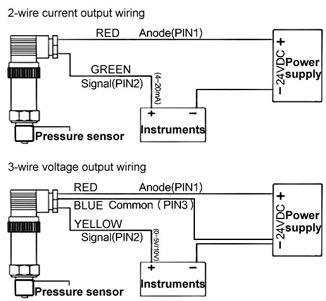
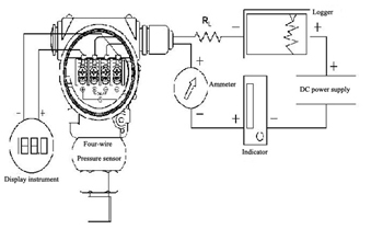
The two-wire pressure sensor is relatively simple, and customers generally know how to wire. Connect a line is to the positive pole of the power supply, and the other line that is the signal line connected to the negative pole of the power supply through the instrument. This is the simplest. The three-wire pressure sensor add a wire to the two-wire system. This wire directly connect the negative pole of the power supply, which is more troublesome than the two-wire system. The four-wire pressure sensor has two power inputs and the other two are signal outputs. Most of the four-wire system is voltage output instead of 4-20mA output. The 4-20mA machine called pressure transmitter, and most of them are two-wire system. Some of the signal output of the pressure sensor without amplification. The full-range output is only a few tens of millivolts, and some pressure sensors have an internal amplification circuit, whose full-range output is 0-2V. As for how to connect to the display meter, it depends on how large the meter's range is. If there is a gear position that matches the output signal, we can use it to measure directly. Otherwise, we should add a signal adjustment circuit. The difference between the five-wire pressure sensor and the four-wire system is small, and there are fewer sensors on the market with five-wire systems.
power supply +, power supply -, feedback + and feedback -. Current type four-wire connection: power +== power supply +; power supply -== power supply -; signal +== feedback +, signal -== feedback -. Current type two-wire connection: power supply +== power supply +; signal +== feedback +, power supply -== feedback -. Voltage type three-wire connection: power +== power supply +; power - (signal -) = = power supply - signal + = = feedback +, power - (signal -) = = feedback -.

The pressure sensor can directly connect with the frequency converter. By connecting the pressure sensor to the signal loop, you can use the 24V power supply on the frequency converter.
The correct wiring method is useful for measuring the pressure of the measure medium accurately. The wiring of the pressure sensor depends mainly on the set measurement method and the range module. In general, pressure sensors often use shielded twisted pair cables to connect analog signal cables, which not only reduces the interference in the noisy environment of the construction site, but also reduces the error caused by the measure medium. In order to prevent the potential difference between the two ends of the analog quantity from producing interference analog signal, one end of the analog quantity must be grounded to avoid this situation.

The two-wire pressure sensor is relatively simple, and customers generally know how to wire. Connect a line is to the positive pole of the power supply, and the other line that is the signal line connected to the negative pole of the power supply through the instrument. This is the simplest. The three-wire pressure sensor add a wire to the two-wire system. This wire directly connect the negative pole of the power supply, which is more troublesome than the two-wire system. The four-wire pressure sensor has two power inputs and the other two are signal outputs. Most of the four-wire system is voltage output instead of 4-20mA output. The 4-20mA machine called pressure transmitter, and most of them are two-wire system. Some of the signal output of the pressure sensor without amplification. The full-range output is only a few tens of millivolts, and some pressure sensors have an internal amplification circuit, whose full-range output is 0-2V. As for how to connect to the display meter, it depends on how large the meter's range is. If there is a gear position that matches the output signal, we can use it to measure directly. Otherwise, we should add a signal adjustment circuit. The difference between the five-wire pressure sensor and the four-wire system is small, and there are fewer sensors on the market with five-wire systems.
- Two-wire wiring
- Three-wire wiring
- Others
power supply +, power supply -, feedback + and feedback -. Current type four-wire connection: power +== power supply +; power supply -== power supply -; signal +== feedback +, signal -== feedback -. Current type two-wire connection: power supply +== power supply +; signal +== feedback +, power supply -== feedback -. Voltage type three-wire connection: power +== power supply +; power - (signal -) = = power supply - signal + = = feedback +, power - (signal -) = = feedback -.

The pressure sensor can directly connect with the frequency converter. By connecting the pressure sensor to the signal loop, you can use the 24V power supply on the frequency converter.
The correct wiring method is useful for measuring the pressure of the measure medium accurately. The wiring of the pressure sensor depends mainly on the set measurement method and the range module. In general, pressure sensors often use shielded twisted pair cables to connect analog signal cables, which not only reduces the interference in the noisy environment of the construction site, but also reduces the error caused by the measure medium. In order to prevent the potential difference between the two ends of the analog quantity from producing interference analog signal, one end of the analog quantity must be grounded to avoid this situation.

